Verilog To Schematic Converter
Verilog code for decoder Verilog circuit code schematic digital Verilog parameters
Draw the circuit corresponding to the Verilog module | Chegg.com
Solved draw the circuit corresponding to the verilog module Verilog: binary to gray converter behavioral modelling using case Verilog circuit code write module below separate structural turn create using style transcribed text show xy file
Verilog clock module corresponding circuit draw solved transcribed text show bit
Verilog adderDraw the circuit corresponding to the verilog module Verilog to schematic converterVerilog parameters.
Getting started with the verilog hardware description languageVerilog code for full adder Verilog code for serial adder circuitSolved 2. (a) write a verilog description of the circuit.

Verilog to vhdl converter download: a small utility that can be used
Verilog decoder codeSolved 5.2 write a structural verilog module for the Verilog to schematic converterSchematic verilog code converting compile vote unsuccessful down favorite.
Verilog corresponding circuit draw module below transcribed text showSolved create a verilog model that represents the circuit Solved: design the following circuit. write verilog code a...Verilog code circuit write following demo simulation run.

Digital verilog electronic circuit simulation
Verilog code for bcd to excess 3 converter 13+ pages solution in doc [1Verilog behavioral modelling Part-1 verilog examples for sequential circuitsSolved verilog code for the following schematic, the.
Verilog synthesisVerilog to schematic converter Simple comparatorHow to generate schematic file from verilog source in xilinx.

Verilog schematic following code solved assignments previous two behavioral
Verilog code of the transistor model moduleVerilog schematic code compile converting unsuccessful Verilog circuit hardware started getting language description articles figureSolved 4. draw the circuit corresponding to the verilog.
Draw the circuit corresponding to the verilog moduleVhdl verilog converter screenshot apr Verilog cheggVerilog binary modelling testbench.

Verilog solved module circuit shown transcribed
Verilog: binary to gray converter structural/gate level modelling withSolved question 6: (verilog for circuit schematic Transistor verilogVerilog for full adder.
Verilog vhdl comparator code circuit example logic implements tutorial simple tutorials icarusVerilog code for parallel to serial converter Solved a) write a verilog module for the circuit below using-clk_divider design in verilog hdl and related symbol.

Verilog vhdl compares adder
Converting verilog code to a digital circuit schematic.mp4Solved 1. write complete verilog code (i.e complete module) .
.


Draw the circuit corresponding to the Verilog module | Chegg.com

Digital Verilog Electronic Circuit Simulation

Solved Question 6: (Verilog for circuit schematic | Chegg.com

Solved a) Write a Verilog module for the circuit below using | Chegg.com
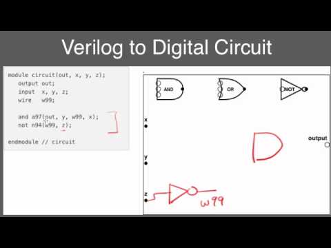
Converting Verilog code to a digital circuit schematic.mp4 - YouTube

Solved 4. Draw the circuit corresponding to the Verilog | Chegg.com